| Home | ||
| • | Lens Tour | |
| Espańol | ||
| Slovensky | ||
| Scenic | ||
| Travel | ||
| Life | ||
| Sports | ||
| Cars | ||
| Aircraft | ||
| Ships | ||
| Candid | ||
| Other | ||
| Equipment | ||
| Ordering | ||
| Links | ||
| About Me | ||
 |

A guided tour through the inner workings of the EF-28-105 USM |
| These are the main
parts of 28-105 USM. Almost everything I have written here is based on my own
understanding and taking apart the lens. I used the Canon Lens Work II book for some
reference information. For a more technical explanation, please refer to Canon's Lens Work II book or the newest EF lenses brochure. |
|
|
Metal the focus key I was surprised to see metal inside this lens when I took it apart. There really is more metal in here than most people think. The focus key is made of metal, presumably because plastic would wear down with all of the key's channels. There are also two cams inside of the key and one outside (not visible in the picture), but the metal one has the most channels and the greatest travel during zooming. Aout half of the elements are contained within this metal focus key. The other half are in the focusing groups, directly in front. |
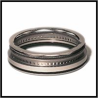 figure 2 |
Ring
Ultrasonic Motor 62mm M-1 It is hard to believe that this is a motor. Well, it is. This is the M-1 ring-USM, which is pretty much the standard. Many common lenses have this very motor, from the 28-105 f/3.5-4.5 and 85 f/1.8, to the 300 f/4L and 70-200 f/2.8L. The 62mm M-1 is dwarfed by its older brother, the 77mm L-1, used in such monster lenses as the 50 f/1.0 and 1200 f/5.6. The M-1 is much easier and cheaper to make than the L-1, but they both use the same basic technology. Although the M-1 might seem puny compared to the L-1, there is a smaller version yet. The Micro-USM is newer and much cheaper than the even the M-1. It, however, uses different technology that makes it operate differently than the M-1and L-1, which are both ring-type designs. For example, the micro-USM lenses like the 28-80 II, II, & IV do not have Full Time Manual (with only one exception, the 50 f/1.4) |
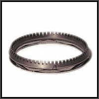 figure 3 |
the Stator & pressure spring The notches edges of the USM stator fit snugly against the USM rotor. A spring-loaded bayonet mounting plate maintains the pressure which ensures that the stator is firmly in place against the rotor. The stator does not move during operation, hence the name stator, which is very similar to stationary. |
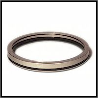 figure 4 |
the Rotor The rotor is the part that rotates. The stator fits above it, with the notched surface against the a small lip on the top surface of the rotor. This is the only part of the motor that moves. What could possibly be more simple than a motor which is comprised of only two metal rings? |
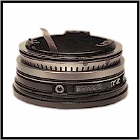 figure 5 |
Put it all
Together how it works The stator vibrates as a current is applied, but does not rotate. The vibrations of the stator, combined with the pressure against the rotor, cause the resulting frictional forces to rotate the rotor, which turns the output ring, moving the elements and focusing the lens. |
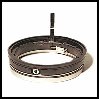 figure 6 |
the Output Ring
& transmission After the stator and rotor come the output ring. A motor is useless without some kind of transmission, and this is it. The black output ring contains three symmetrically positioned metallic rollers. It receives input from either the rotor or the manual focus ring, and then moves the focusing group at the front of the lens. If you take a close look at figure 1, you can see the "transmission" from the output ring at the bottom to the focusing group at the top. |
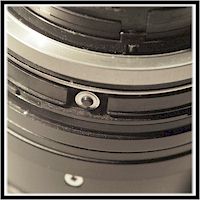 figure 7 |
Full Time
Manual don't leave home without it The output ring is sandwiched between the M-1 USM and the manual focus ring (under mild pressure). Either the USM rotor or the manual focus ring turns (while the other remains stationary), rotating the three rollers, which move the output ring. The FT-M mechanism, like the USM assembly, is so amazingly simple. note: The L-1 motor does not have FT-M, but rather Electronic Manual Focusing (E-M) |
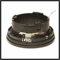 figure 8 |
Returning
Distance information It is very interesting to note that this lens is capable of returning distance information to the body. Canon won't comment, but there is a pattern of contacts arranged under the USM rotor, directly behind the distance scale. Removing the distance scale and motor, it is easy to see this. As the output ring and distance scale rotate, so does a set of contacts, completing the circuit. When the lens is focused and the distance changes, the pattern of the contacts is different. There is a unique pattern of the contacts for each distance capable of being returned. |
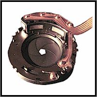 figure 9 |
EMD electromagnetic diaphragm Canon EF and TS-E lenses all use deformation stepping motors to control the aperture blades. The aperture is controlled by an electronic pulse, and the result is very quiet and precise operation. Other than the initial signal, control over the aperture is handled entirely within the lens. As this picture shows, the 28-105 USM has a five bladed aperture. This is probably a fairly standard Canon EMD unit. |
 figure 10 |
the Photocoupler explained by Chuck Westfall If you look closely at figure 10, you'll notice a small mechanism positioned above a semi-circular strip. This is a photocoupler, in other words a device consisting of an LED and a photo-transistor. The semi-circular strip is an encoder ring covered with alternating reflective and non-reflective strips. [sw: the alternating strips are very small, I had to use my loupe (see figure 12) to see them] This assembly is used during the autofocus drive process as
follows: |
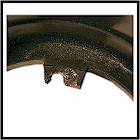 figure 11 |
The Weak
Link the part that broke This 28-105 USM was dropped from a relatively low altitude onto a hard surface. Optically and mechanically, the lens seemed to be fine. However, there are three plastic tabs which basically hold the plastic barrel near the mount and distance scale onto the rest of the lens. Those three plastic tabs shattered as shown in the picture, ruining an otherwise good lens. I have been told by a visitor to this site that even the higher quality zooms still have this same type of design (although with more connection points). This person dropped a 28-70L, and it broke in a similar manner. The lens probably could have been fixed, but I was looking for something to take apart for this tour, and I was willing to pay for it. |
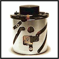 figure 12 |
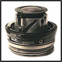
What Now? It makes a good loupe! Near the 105mm setting, without the focusing groups, this part of the lens can focus on the plane directly in front of the metal barrell. Fine focus adjustments can be made by zooming (turning the black ring at the top). This is currently at the 28mm setting; the rear element (shown protruding on top) is flush with rest of the lens at 105mm. The only drawback is that it does not cover the full frame. It does, however, have high magnification. I don't know what the power is, but it is more than 8x. |
| last modified 06/08/03 10:56 AM |